
How To Construct Serial Loopback Adapter Plugs
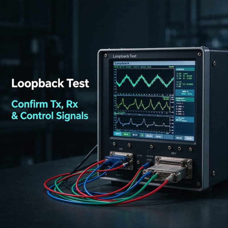
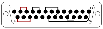
Reading the diagrams: pins marked in red are the data lines, Tx and Rx, and are necessary for the loopback and BERT testing. All other pins are for modem control signal tests and are not necessary to connect unless you wish to test those signals.
Why Use a Serial Loopback Adapter?
A serial loopback plug is a simple test fixture that redirects a port's own output back to its own input. Instead of wiring the connector to a remote modem, printer, instrument, or another computer, the adapter joins the transmit lines to the receive lines inside the connector shell — and optionally loops the modem control lines back as well. With only a connector and a few short jumper wires, you can exercise the serial port end to end without any external device on the other end of the link.
- Verify transmit and receive hardware — with Tx jumpered to Rx, everything the port sends out comes straight back; a terminal emulator or test program compares the echoed data with the original, proving the UART, transceiver, connector pins and onboard wiring are working correctly.
- Run bit-error-rate (BERT) testing — loopback is the standard setup for BERT tools that stream a known data pattern and count errors. It is used to characterize signal quality, baud-rate stability and noise margins on RS-232, RS-422, RS-485 and RS-530 links.
- Test handshake and modem control signals — jumpering RTS to CTS and DTR to DSR/DCD (and RI where applicable) makes the port believe a remote device and its control handshakes are present, so software can exercise flow-control and modem-status routines without external equipment.
- Isolate faults during troubleshooting — if the port passes loopback but fails when connected through a cable or to a device, the problem lies in the cable, the remote unit or the wiring — not the port itself. Loopback thus narrows the fault to one side of the link.
- Support manufacturing and field QA — loopback plugs are fast, low-cost fixtures for production-line testing, pre-shipment checks and service-rack diagnostics.
- Confirm driver and OS configuration — a successful loopback also confirms that the serial driver, COM port mapping and port settings (baud rate, data bits, parity, stop bits, flow control) are configured correctly on the host side.
Two levels of loopback:
- Data-only (minimum) — jumper Tx to Rx; on differential interfaces, jumper Tx+ to Rx+ and Tx− to Rx−. This is enough to validate data transmission and run BERT.
- Full modem loopback — also jumper the handshake and control pins as listed in each diagram below, so flow-control and status signals are returned to the port. Connect only the pins your test requires.
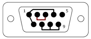
DB-9 RS-232 Loopback Connection (TIA-574)
Connect pins:
- 2 to 3 — Rx to Tx
- 1 to 4 to 6 — DCD to DTR to DSR
- 7 to 8 to 9 — RTS to CTS to RI
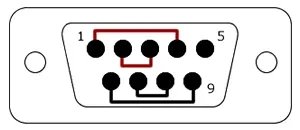
DB-9 RS-422 / RS-485 Loopback Connection
Connect pins:
- 1 to 4 — Rx+ to Tx+
- 2 to 3 — Rx− to Tx−
- 6 to 9 — RTS+ to CTS+
- 7 to 8 — RTS− to CTS−
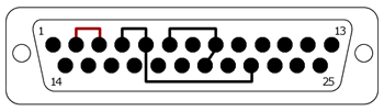
DB-25 RS-232 Loopback Connection (EIA-232)
Connect pins:
- 2 to 3 — Tx to Rx
- 4 to 5 to 22 — RTS to CTS to RI
- 6 to 8 to 20 — DSR to DCD to DTR
DB-25 RS-422 / RS-485 / RS-530 Loopback Connection
Connect pins:
- 2 to 3 — Tx− to Rx−
- 14 to 16 — Tx+ to Rx+
- 5 to 4 — RTS− to CTS−
- 13 to 19 — RTS+ to CTS+
- 10 to 22 to 23 — DCD+ to DSR+ to DTR+
- 6 to 8 to 20 — DCD− to DSR− to DTR−
Related products: Tittron USB to RS-232 / RS-422 / RS-485 adapters and hubs — sent straight from the factory. Product appearance and specifications are subject to change without prior notice.
Need the full datasheet or samples?
Tell us the model and quantity — we will send documentation and quotation.